 Menu
Menu


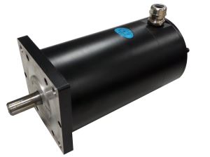
DCYJ-208
-
Min Order
1
-
Product Unit
Pieces
-
Origin
China Mainland
-
Payment


- Contact Now Start Order
- Favorites Share
- Description
Product Detail
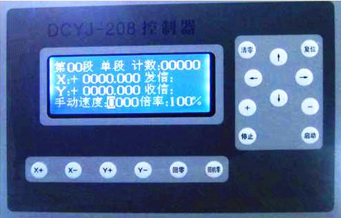
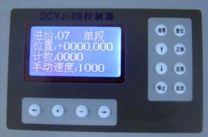
Product Model:DCYJ-208
The core of the controller is embedded computer. It is Chinese LCD human-computer interface and featured with simple operation and high flexibility. All operations are done by the Chinese program setting that it can fill out the reminding form of the controller to complete the program without any commands. It is equal to a PLC add a screen integration. However, compared with PLC, it is much easier that even a common operator can operate it. Besides, it is interrupted resistance, which can work stably even under the welding condition.
Main performance
1. Control two stepper motors or servo motors, rotate speed and angle can be set as you required.
2. Positive and negative protection for the motor
3. Return to coordinate zero
4. Return to mechanic zero
5. Counter automatically and it can set the quantity for the process workpiece
6. Circulated process, and the circle times can be set
7. 20 individual output ports
8. 35 individual input ports
The specification of the controller is as below:
1. Input power supply:DC24V,DC5V
2. Control accuracy:1 step
3. Environment temperature:—10~+40?
4. Relative Humidity :80%(25?)
5. Size:230*150*34(Width*Height*Thick)mm
6. Weight:1kg
Performance of Keys(?)Controller panel and keys

1? Press‘?’or‘?’key, It means to move to left or right.
2?Press‘?’or‘?’to display the previous or next page.
3?Press +’or‘-’:The parameter in the cursor will be plus or minus1 after press it.
4?The counter will be 0 when press the clear key.
5?The controller will be at original display when press re-set key.
6?Press X+’?‘X-’?‘Y+’and‘Y-’ key, the motor will rotate clockwisely or anti-clockwisely, and it will stop when the loose the key.
7?The motor will return to 0 position when press the key of return to zero
8?The motor will return to mechanic zero when press the key of return to mechanic zero
9?It will start to process automatically when you press the start key.
10?Press stop key, it will switch to single step, single time and continuous
11?It will stop temporarily when press stop key, and re-press the stop key, it will go on processing. The three ways of continuous, single process or single can be switched when the motor is not running and it is not stopped temporarily.
(?)Outside connecting keys and switch signal
1?The controller provide the outside connecting keys below:
A?Start (outside connected) key: It has same function as the start key on the panel, and it is series connected.
B?Stop (outside connected) key: It has same function as the stop key on the panel, and it is series connected.
C?Return to zero key (outside connected): It has same function as the stop key on the panel, and it is series connected. The X, Y motor will return to the 0 coordinate position with manual speed when press the key, you can firstly return X or Y axes. It will firstly return X axes if you press X+ or X- while if you press Y+ or Y-, it will firstly return Y axes.
D?Return to mechanic zero key (outside connected): It has same function as the return to mechanic zero key on the panel, and it is series connected. The X, Y motor will anti-clockwise rotates to the negative limit switch or mechanic zero switches with manual speed when press the key, and then the motor will clockwise rotate slowly out of the mechanic zero switch and clear the position. You can firstly return X or Y axes. It will firstly return X axes if you press X+ or X- while if you press Y+ or Y-, it will firstly return Y axes.
E?X+(outside connected) key : It has same function as X+ key on the panel, and it is series connected. The X motor will rotate clockwisely when press the key, and the speed will reduce until stop when loose the key.
F?X- (outside connected) key : It has same function as X+ key on the panel, and it is series connected. The X motor will rotate anti-clockwisely when press the key, and the speed will reduce until stop when loose the key.
G?Y+(outside connected) key : It has same function as Y+ key on the panel, and it is series connected. The X motor will rotate clockwisely when press the key, and the speed will reduce until stop when loose the key.
H?Y- (outside connected) key : It has same function as X+ key on the panel, and it is series connected. The Y motor will rotate anti-clockwisely when press the key, and the speed will reduce until stop when loose the key.
Note1: the definition of single process, single time and continuous
Single process: It will temporarily stop when process one page, it needs to press start key to implement next page.
Single time: It will temporarily stop when finish the whole processing procedure, it needs to press start key to implement next whole procedure.
Continuous: It will process continuously until the required quantity is finished or it will stop when you press stop key.
Note2: There are two kinds for returning to the mechanical zero
(1)The motor is not out of signal switch of the mechanical original point when press the “return to mechanic zero'' key, the drawing is as below
a?It is effective that the motor anti-clockwise rotate to mechanic zero signal by manual speed.
b?It is ineffective that the motor anti-clockwise rotate 20 steps, the mechanic original point signal should be effective at this time.
c?It is ineffective that the motor clockwise rotate the mechanic signal slowly

(2)The motor will be exceed the mechanic signal switch when press the key of return to mechanic zero

a?It is effective that the motor anti-clockwise rotate to negative limit switch by manual speed.
b?It is effective that the motor clockwise rotate to the mechanic signal slowly.
c?It is ineffective that the motor clockwise rotate to the mechanic original signal slowly.
2?The controller has the ports for outside input/output signal
Receive 1: If it is on, it will continue to process when the waiting signal is low.
Receive 2: If it is on, it will continue to process when the waiting signal is low.
Receive 3: If it is on, it will continue to process when the waiting signal is low.
Receive 4: If it is on, it will continue to process when the waiting signal is low.
Receive 5: If it is on, it will continue to process when the waiting signal is low.
Receive 6: If it is on, it will continue to process when the waiting signal is low.
Length limits foot: When the setting of the controller is length limited, it will be esc the process of the step if the receiving signal is low.
Positive limit foot: The motor will stop when the signal is low during the motor running clockwisely, the controller display positive limit and waiting, press re-set key.
Negative limit: The motor will stop when the signal is low during the motor rotate anti-clockwise. The controller display positive limit and waiting, press re-set key.
Mechanic zero position: It is used to return the mechanic zero, each X and Y axes have one.
Note:
1? All keys, receive, limit switch and mechanic zero signal adopt normal touch point without interlock function, and it can be effective under lower power level.
2?the difference between return to zero and return to mechanical original point:
Return to zero means the motor return to the position of “0'', the distance and the direction that the motor run is related to the position that the controller set.
For example, if the controller position is set as +0526.780, press the “return to zero'' key, the motor will run anti-clockwise up to 526.780, and then stop, and if the controller position is set at -0132.255, press the press the “return to zero'' key, the motor will run clockwise up to 132.255 and then stop.
Return to mechanic zero means the motor returns to mechanical original position of signal switch, the distance and the direction that the motor run is related to the position of mechanic original position of switch signal but is not related to the position that controller indicated.
?? LCD Parameter Setting
Press‘?’?‘?’?‘?’or‘?’to move it and press +’or‘-’ to plus or minus the display, or exchange between the on and off.
(-)?Initial Page:

00 step: It means the processing is on which step, 00 means it is not on processing while 01, 02…. means the processing is on 1st, second, third…. step.
Continue: It means it is at continuous processing condition (when the motor is not working and it is not at temporary stop). It may display the stop temporarily, single step, and single time and continue way when press the stop key.
Counter: The already processed quantity, press rest and stop key at same time, and then loose the stop key after loose the re-set key, it will clear.
“X'':It means X motor, + means the deviate the distance of zero at positive direction, - means deviation distance of zero, ‘0000.000’means the position, the unit is mm or degree, press clear, it will clear all to zero.
“Sending signal:It means all present opening signal sending port ?
“Y'':It means Y motor,‘++ means the deviate the distance of zero at positive direction, - means deviation distance of zero, ‘0000.000’means the position, the unit is mm or degree, press clear, it will clear all to zero.
“Receiving signal'': It means all present opening signal receiving port ?
“Manual speed'':It means rotate speed of the motor when press‘X+’?‘X-’?‘Y+’?‘Y-’, the unit is HZ.
“Multiply factor'':The motor running coefficient, it can be used to adjust the speed of the motor indirectly?
(?)Process page (from 01 to 99):

01 step: It means which step, the value is from 01 to 99, the direct line means the process way, it can switch by off, direct line, clockwise round, anti-clockwise round, length limit and screw while length limit is one kind of the direct line.
Sending signal means the setting of signal sending, the choice of the number can be from 0 to 8, if it is 0, it will shield all signal port and then it won’t send signal what ever his setting is on or off, in other word, it has 8 signal sending port, off means the signal sending is off while on means it is on.
X has same means as defined in the initial page.
Receiving signal means the setting of signal receiving; the number can be from 0 to 6, it will shield all signal port and then it won’t receive signal what ever his setting is on or off, in other word, it has 6 signal receiving port, off means the signal sending is off while on means it is on.
Y has same means as defined in the initial page.
Prolong means the prolong time setting, the unit is second, the prolong action will be done after the signal sending, receiving and motor moving, in other word, it is the last action.
R means the setting of the radius, when the process step is clockwise or anti-clockwise round, it is effective, but it won’t be effective when the setting is direct line or length limit.
Speed means the running speed of the motor, the max setting is 59999HZ (59999 impulse per second)
Note:
1?The X, Y and R has different meaning when the setting is screw:
‘X’:means the screw length,the unit is mm;
‘Y’:screw width,he unit is mm?the max is 0065.535;
‘R’:the head quantity of the screw,the 1st number before the decimal point means the quantity of the head, and number after the decimal point means which head of the screw which can not bigger than the total number of the heads. e.g. 0002.100 mean the 1st head of 2-head screw.
2?Length limit is a special kind of direct line; it will check the length limit signal during the motor running, when the signal is checked, the motor will stop running and go on with other action. The controller has the step from 01 to 99, totally 99 working pages and it can set 99 processing step, all settings in each page is same. Press the start key to start the process from 01 step to 99 step, we take 01 step as example to instruct the procedure.
e.g. 1:
01 step: direct line, it will implement the page automatically and the processing way is direct line. When it is off, it won’t implement the page the setting of prolong, speed, distance, send signal and receive will not work.
In the example is direct line, it will implement the page under automatic processing.
Send signal: 1~8 can set as you required, controlling the signal sending 1, 2, 3, 4, 5, 6, 7 and 8. “On'' means the controlled signal sending is on while off means off.
In the example, the sending signal 1 is off, it means the signal sending port is off, if it is on, the sending signal foot is low power when the controller implement here.
Receive signal: It can be set as you required from 0 to 6, check the receive port of 1 or 2?3?4?5?6, 0 means not to check the receiving signal. When it is on, it means the controlled signal receiving port is on while off means off.
In the example, the receive signal is off which means the port is also off, if it is on, the controller will wait when implement to receive the signal until the receive signal 1 is low power level.
Length:The motor moving distance;
After the X’ is X motor length or degree, if it is forward, the motor will rotate clockwisely, if it is backward, it will rotate anti-clockwisely. If it is +’or‘-’, it will determined by the actual situation to rotate clockwise or anti-clockwise.
After the Y’ is Y motor length or degree, if it is forward, the motor will rotate clockwisely, if it is backward, it will rotate anti-clockwisely. If it is +’or‘-’, it will determined by the actual situation to rotate clockwise or anti-clockwise.
The X is +0032.328 in the example, the motor will rotate to 32.328mm, if the original X motor position is +0010.000, the motor will clockwise rotate 22.328mm.
The Y is+0010.000 in the example, the motor will rotate to 10.000mm, if the original Y motor position is+0030.000, the motor will clockwise rotate 20.000mm.
Prolong: The waiting time after the signal sending, receiving and motor moving, unit: second.
The example is 1.0 ,means 1.0 second?
R: Radius, when the processing way is direct line or length limit, the setting is ineffective but it is effective when the setting is clockwise or anti-clockwise round, the unit is mm.
The example is 0000 for the processing way is direct line.
Speed: The rotate speed of the motor, if the data is 0, it means the motor will run with the slowest speed.
The speed in the example is 6000,>it means the motor X will run with 6000HZ.
Note:
1?Each step has four implements from send signal, receive signal, motor move and prolong. If the send signal is off, it will flick to receive signal, and if the receive signal is off, it will go direct to the motor move, and then prolong, if the prolong time is 0, it will go to the next step. If the length or rotate angle of X and Y motor is o, the motor won’t rotate.
2?If the signal sending is on, it will send signal with low power level (100mA drive, the signal sending to DC24V relay, the +24v of the controller wiring to another one of the DC24V relay to pickup it) when the sending signal is on while is off, the signal sending will suspended to flick the DC24V relay. The signal sending is DC24V collector open circuit output.
3?If the signal receiving is on, the controller will wait for the low power level, the signal receiving is finished when the low power level is checked. The low power level means DC 24V grounding.
4?The signal receive port requirement:
a. Low power level or grounding short circuit with 24 V, the power level should be less than 1.0V;
b. The power level should be more than 10V or the foot suspended if the signal is ineffective;
c. The last time of the signal should be more than 15ms (0.015 second)
5?There are many ways to produce the signal in the signal receive port:
a. It can adopt touch switch similar as travel switch, the 2 feet of the touch switch connect with the signal receive foot of signal receive and 24V grounding foot of controller.
b. It can also adopt DC24V approximate switch or its power supply controller, +24V, its grounding controller, 24V, and its signal receive foot. The common ones can be used in the market are from DC8 to 36V.
(?)?Special parameter setting

Circulated process: If the setting is on, the process will be done as the setting required, and if it is off, all settings will not work, the setting parameter is including cycle beginning and ending, cycle times.
Cycle: The initial and the last cycling step. If the setting is not correct, such as the beginning is bigger than the ending or the ending is more than 30, there will be reminding said your cycle setting is wrong when you press the start key, you can press any key to enter into the cycle setting page at that time.
Process quantity: The setting process quantity, usually it is more than two times. It is effect when the cycle setting is on.
It is off in the example; it means there is not cycle setting even there is vale in cycle step.
If the cycle process is on, it will circulate the cycle step when implement the 01 step, the procedure is as below, 02-03-04-02-03???04-02-03-04…..
The step 02 to 04 will be repeated 5 times.
X motor step length: Set each step that the stepper motor move that react as mechanic distance or angle, the setting is related to the mechanic gear ratio and stepper motor sifting, it can not change once the gear ratio and the sifting is determined.
When it is wrong set, e.g. the 0.000/100or 1.000/000 (there is 0 happened in the denominator or numerator) , there will be reminding said to set the length correctly, you can press any key to enter into the X motor step setting interface.
It is 0.010/001 in the example; it means when the X motor move 1 step, it will react as forward or backward 0.010mm or means clockwise or anti-clockwise rotate 0.010 degree.
Y motor step length: Set each step that the stepper motor move that react as mechanic distance or angle, the setting is related to the mechanic gear ratio and stepper motor sifting, it can not change once the gear ratio and the sifting is determined.
When it is wrong set, e.g. the 0.000/100or 1.000/000 (there is 0 happened in the denominator or numerator) , there will be reminding said to set the length correctly, you can press any key to enter into the X motor step setting interface.
It is 0.010/001 in the example; it means when the Y motor move 1 step, it will react as forward or backward 0.010mm or means clockwise or anti-clockwise rotate 0.010 degree.
e.g. 2:
If the gear ratio of X motor is 2:1 (speed up) , the sifting is 2 and the motor is 2 phase combined stepper motor (step distance 1.8 degree, if it is 3 phase or 3 phase combined step, it is not same), the calculation is as below: (2×360)/(200×2)=1.800/001, in other word, each motor step is equal to 1.8 degree.
e.g. 3:
If the gear ratio of Y motor is 2:1 (speed reduced) , the sifting is 2 and screw width is 4 mm, and it is 3 phase stepper motor (3 phase, 6 step, the step angle is 0.75 degree), the calculation is as below: 4/(2×4×480)=0.025/024
Note:
The step length should be simple reduction from the fraction, in other word, the denominator is the smaller the better, as the e.g. 3, it is not good to be 0.100/096.
(?)?Special parameter setting 2

X clearance compensate: It is used to improve the processing accuracy to remove the clearance among the gear, it is set base on the accuracy of the mechanic, and the unit is mm.
Y clearance compensate: It is used to improve the processing accuracy to remove the clearance among the gear, it is set base on the accuracy of the mechanic, and the unit is mm.
Motor speed up: It is used to reduce or decrease the speed. Usually, it will use slow when the sifting is small while the sifting is big, it will adjust base on actual situation to switch as middle or quick. It may result the motor can not run or run unstably if it is not adjust properly.
Non-used page: It is used to open the non-used page, if the setting is off, the 01 to 30 step is off, the pages will not display, if you want to display the parameter, it should set it at on.
(?)?Special parameter setting 3

Process quantity: It is used to set the total processing quantity, it is the implement times from the 1st step to the last step, if the setting is 0000, it will process continuously until press stop key, the unit is piece, the max setting is 59999.
Tail length: It is only used to make screw to set the length of screw tail.
Tail height: It is only used to make screw to set the height of screw tail.
??Automatic operation
Set the parameter as above and fix the workpiece, the press the start key, then press the start key, it will process, the outside connected start key can also realize the function.
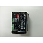
??Outside connected input and output port definition

(?)9-core outlet(power supply input)
1?2 foot:+24V 6?7 foot:24V grounding
4?5 foot:+5V 8?9 foot :5Vgrouding
Note: +5V and 5V ground should be wind together, the length should be within 20 cm and they can not be bundled together with other wiring.
(?)25-core-contact pin (output outlet)
1 foot: signal sending 3
2 foot: signal sending 2
3 foot: signal sending 1
4 foot: Empty
5 foot: Empty
6 foot: Empty
7 foot: Empty
8 foot:XMC, x-axes direction signal
9 foot:XCP, x-axes direction signal
10 foot:YMC, y-axes direction signal
11 foot:YCP, y
12 foot:-24V
13 foot:-24V
14 foot:+24V
15 foot:+24V
16 foot:+24V
17 foot:+24V
18 foot: Empty
19 foot: Empty
20 foot: Empty
21 foot: signal sending 8
22 foot: signal sending 7
23 foot: signal sending 6
24 foot: signal sending 5
25 foot: signal sending 4
(?)25-core-contact pin (output outlet)1 foot:-24V
2 foot:-24V
3 foot: Signal recieving1
4 foot: Signal recieving2
5 foot: Signal recieving3
6 foot: Signal recieving4
7 foot: Signal recieving5
8 foot: Signal recieving6
9 foot:length limit control signal
10 foot:negative limit
11 foot:Connect to the other end of the start button
12 foot:Connect to the other end of the stop button
13 foot:Connected to the end of X+ button
14 foot:Connected to the end of X- button
15 foot:Connected to the end of Y+ button
16 foot:Connected to the end of Y- button
17 foot:Connected to the end of return to zero button
18 foot:Connected to the end of return to mechanic zero button
19 foot:X axes mechanic zero signal
20 foot:A signal(Press the encoder signal A, it is used to process screw)
21 foot:Y axes mechanic zero signal
22 foot:positive limit signal
23 foot:Z signal(Press the encoder signal Z, it is used to process screw)
24 foot:+24V
25 foot:+24V
Note:
1?All the wiring voltage of the relay is DC24v, and all the other wiring end and +5V of 2 stepper motor drive is connected to 24V.
2?Both the other ends of the buttons and limit switches of the drive is connected to 24V grounding.
3?All buttons and limit switches use touch point without interlock function.
Note:
1?It is effective that all receiving signal is lower power level or grounding short circuit with 24V
2?It will send signal with low power level(100mA drive, the signal sending to DC24V relay, the +24v of the controller wiring to another one of the DC24V relay to pickup it) when the sending signal is on while is off, the signal sending will suspended to flick the DC24V relay.
3?The signal sending is DC24V collector open circuit output. All wiring voltage of the relay is DC24V, and the other relay wiring end of controller is connected to +24V.
4?25-core outlet foot 9 and 11 foot is the impulse signal of stepper (or servo) motor. It is connected to one CP foot of stepper or servo drive, some motor drive called PULE or CP, PULE, CW, CW-. 25-core outlet foot 8 and 10 is the direction signal of stepper (or servo) motor. It is connected to one UD foot of stepper or servo drive, some motor drive called MC-, DIR- or MC, DIR, CCW, CCW-. The +24V foot of the controller is connected to the CP+ and UD+ foot of drive, some motor drive called it as PULE+?DIR+?MC+ or OPTO?+5V?COM?CW+?CCW+. Usually, the signal input power level of the controller is 5V logical power level. The output logical power level of this controller is 24V but it can connect directly to the drive with 5V logical power level, and it doesn’t to add current limit resistance. It has better interruption resistance performance compared with the 5V logical power level as the impulse signal and direction signal have been treated.
5?All buttons and limit switches use touch point without interlock function.

-
DC Side Motor 1 Pieces / (Min. Order)

-
DC Door Motor 1 Pieces / (Min. Order)
-
Door Motor 1 Pieces / (Min. Order)
-
Door Motor 1 Pieces / (Min. Order)
-
Door Motor 1 Pieces / (Min. Order)
-
DCYJ-08 1 Pieces / (Min. Order)
-
DCH20403 1 Pieces / (Min. Order)
-
19-ZDC-07-HD1 1 Pieces / (Min. Order)

-
21-ZDC-07-HHT2 1 Pieces / (Min. Order)

-
64-ZDC-07-MEDG25 1 Pieces / (Min. Order)

-
66-ZDC-06-KS 1 Pieces / (Min. Order)

-
55-ZDC-03-NF 1 Pieces / (Min. Order)

-
DC Torque Motor 1 Pieces / (Min. Order)
-
Z4 DC Motors 1 Pieces / (Min. Order)
-
Dc Motor-16HY 1 Pieces / (Min. Order)
-
Dc Motor-14HY 1 Pieces / (Min. Order)
-
Dc Motor-17HD 1 Pieces / (Min. Order)
-
Dc Motor-23HD 1 Pieces / (Min. Order)
-
Dc Motor-17HY 1 Pieces / (Min. Order)
 Favorites
-
 Stepper Motor With Encoder Feedback
1 Pieces / (Min. Order)
Stepper Motor With Encoder Feedback
1 Pieces / (Min. Order)
-
 CF2034D
1 Pieces / (Min. Order)
CF2034D
1 Pieces / (Min. Order)
-
DCH20403
1 Pieces / (Min. Order)
-
 130ST-M15025
1 Pieces / (Min. Order)
130ST-M15025
1 Pieces / (Min. Order)
-
 130ST-M15015
1 Pieces / (Min. Order)
130ST-M15015
1 Pieces / (Min. Order)
-
 80ST-M03230
1 Pieces / (Min. Order)
80ST-M03230
1 Pieces / (Min. Order)
-
 80ST-M02430
1 Pieces / (Min. Order)
80ST-M02430
1 Pieces / (Min. Order)
-
 80ST-M01630
1 Pieces / (Min. Order)
80ST-M01630
1 Pieces / (Min. Order)
-
 60ST-M01930
1 Pieces / (Min. Order)
60ST-M01930
1 Pieces / (Min. Order)
-
 110S5P261-3010A
1 Pieces / (Min. Order)
110S5P261-3010A
1 Pieces / (Min. Order)
-
 110SH3P243-5203A
1 Pieces / (Min. Order)
110SH3P243-5203A
1 Pieces / (Min. Order)
-
 110SH3P202-4803A
1 Pieces / (Min. Order)
110SH3P202-4803A
1 Pieces / (Min. Order)
-
 110SH3P161-4203A
1 Pieces / (Min. Order)
110SH3P161-4203A
1 Pieces / (Min. Order)
-
 110SH3P128-4203A
1 Pieces / (Min. Order)
110SH3P128-4203A
1 Pieces / (Min. Order)
-
 86SH3P130-5803A
1 Pieces / (Min. Order)
86SH3P130-5803A
1 Pieces / (Min. Order)
-
 86SH3P130-22503A
1 Pieces / (Min. Order)
86SH3P130-22503A
1 Pieces / (Min. Order)
-
 86SH3P101-5803A
1 Pieces / (Min. Order)
86SH3P101-5803A
1 Pieces / (Min. Order)
-
 86SH3P101-2003A
1 Pieces / (Min. Order)
86SH3P101-2003A
1 Pieces / (Min. Order)
-
 130S281-6004A
1 Pieces / (Min. Order)
130S281-6004A
1 Pieces / (Min. Order)
 Frequent updates ensuring high quality data
 Over 5000 customers trust us to help grow their business!


 Menu
Menu