 Menu
Menu


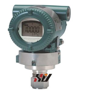
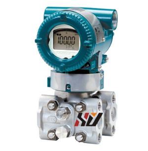
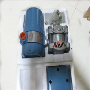
Rosemount 644 Temperature Transmitter
-
Min Order
1
-
Product Unit
Pieces
-
Origin
China Mainland
-
Payment


- Contact Now Start Order
- Favorites Share
- Description
Product Detail
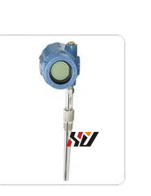
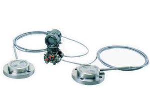
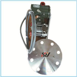
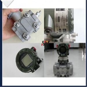
Rosemount 644 Temperature Transmitter
Feature :
1. Attach the thermowell to the pipe or process container wall. Install and tighten thermowells before applying process pressure.
2. Attach necessary extension nipples and adapters to the thermowell.Seal the nipple and adapter threads with silicone tape.
3. Screw the sensor into the thermowell. Install drain seals if required for severe environments or to satisfy code requirements.
4. Pull the sensor wiring leads through the universal head and transmitter. Mount the transmitter in the universal head by threading the transmitter mounting screws into the universal head mounting holes.
5. Mount the transmitter-sensor assembly into the thermowell. Seal adapter threads with silicone tape.
6. Install a cable gland or conduit for field wiring to the conduit entry ofthe universal head. Seal threads with silicone tape.
7. Pull the field wiring leads through the conduit into the universal head.Attach the sensor and power leads to the transmitter. Avoid contactwith other terminals.
8. Install and tighten the universal head cover. Enclosure covers mustbe fully engaged to meet explosion-proof requirements.
Specifications :
LCD Display Installation
The LCD display provides local indication of the transmitter output and
abbreviated diagnostic messages governing transmitter operation.
Transmitters ordered with the LCD display are shipped with the meter
installed. After-market installation requires the meter kit (part number00644-4430-0001), which includes:
• LCD display assembly (includes LCD display, meter spacer,and 2 screws)
• Meter cover with O-ring in place
The transmitters will accept inputs from a variety of RTD and thermocouple types. Refer to Figure 4-1 when making sensor connections. Refer to Figure 4-2 for Profibus installations.Use the following steps to wire the power and sensor to the transmitter:
1. Connect the positive power lead to the .+. terminal. Connect the negative power lead to the .-. terminal.
2. Tighten the terminal screws. When tightening the sensor and power wires, the max torque is 6-in.-lbs (0.7 N-m).
3. Apply power.
Teachnical parameters :


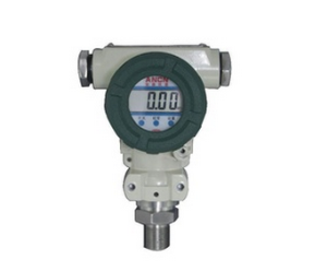
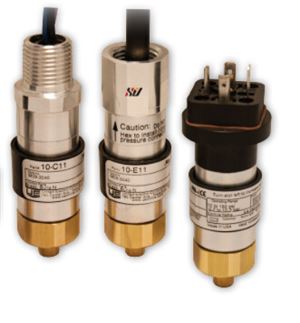
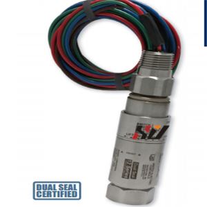
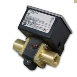
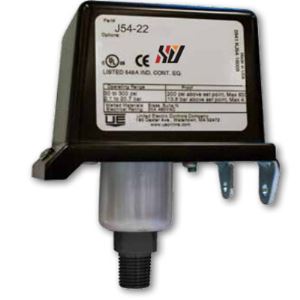
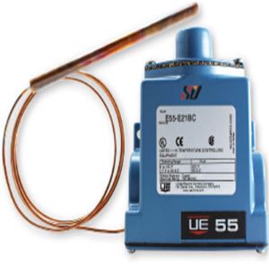
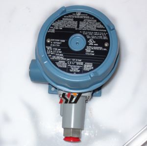
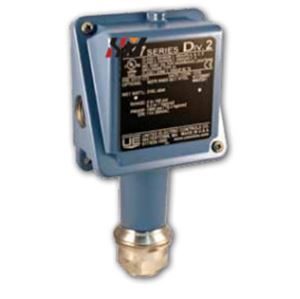
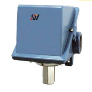
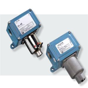
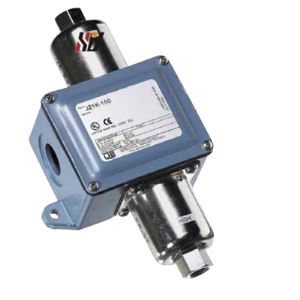
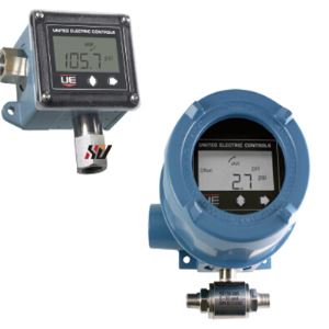
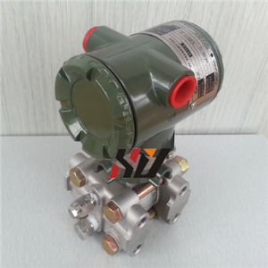
Products show :
.jpg")
.jpg")
.jpg")
.jpg")
Why chose us :


-
UNI800F Peak-holding Instrument 1 Pieces / (Min. Order)
-
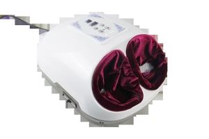
Foot Moxibustion Instrument 1 Pieces / (Min. Order)
-
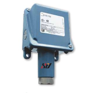
Pressure Switch 1 Pieces / (Min. Order)
-
Pressure-switch 1 Pieces / (Min. Order)

-
UE 10 Pressure Switch 1 Pieces / (Min. Order)
-
UE 12 Series Pressure Switch 1 Pieces / (Min. Order)
-
24 Series UE Pressure Switch 1 Pieces / (Min. Order)
-
54 Series UE Pressure Switch 1 Pieces / (Min. Order)
-
55 Series UE Temperature Switch 1 Pieces / (Min. Order)
-
UE J120 Pressure Switch 1 Pieces / (Min. Order)
-
117 Series UE Pressure Switch 1 Pieces / (Min. Order)
-
J400 UE Temperature Switch 1 Pieces / (Min. Order)
-
J6 UE Pressure And Vacuum Switches 1 Pieces / (Min. Order)
-
UE J21K Differential Pressure Switch 1 Pieces / (Min. Order)
-
UE Temperature Transmitter With Switch 1 Pieces / (Min. Order)
-
EJA110A Differential Pressure Transmitter 1 Pieces / (Min. Order)
-
EJA118W Diaphragm SeaLED Differential Pressure Transmitters 1 Pieces / (Min. Order)
-
EJA118N Differential Pressure Transmitter 1 Pieces / (Min. Order)
-
EJA130A Differential Pressure Transmitter 1 Pieces / (Min. Order)
 Favorites
-
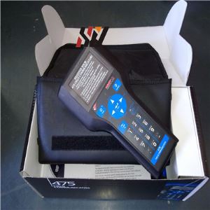
 Rosemount 475 Hart Communicator
1 Pieces / (Min. Order)
Rosemount 475 Hart Communicator
1 Pieces / (Min. Order)
-
 Rosemount 475 Feild Communicator
1 Pieces / (Min. Order)
Rosemount 475 Feild Communicator
1 Pieces / (Min. Order)
-
 EJX510A EJX530A Absolute And Gauge Pressure Transmitter
1 Pieces / (Min. Order)
EJX510A EJX530A Absolute And Gauge Pressure Transmitter
1 Pieces / (Min. Order)
-
 EJX110A Differential Pressure Transmitter
1 Pieces / (Min. Order)
EJX110A Differential Pressure Transmitter
1 Pieces / (Min. Order)
-
 Rosemount 1151 Pressure Transmitter
1 Pieces / (Min. Order)
Rosemount 1151 Pressure Transmitter
1 Pieces / (Min. Order)
-
EJA130A Differential Pressure Transmitter
1 Pieces / (Min. Order)
-
EJA118N Differential Pressure Transmitter
1 Pieces / (Min. Order)
-
EJA118W Diaphragm SeaLED Differential Pressure Transmitters
1 Pieces / (Min. Order)
-
EJA110A Differential Pressure Transmitter
1 Pieces / (Min. Order)
-
UE Temperature Transmitter With Switch
1 Pieces / (Min. Order)
-
UE J21K Differential Pressure Switch
1 Pieces / (Min. Order)
-
J6 UE Pressure And Vacuum Switches
1 Pieces / (Min. Order)
-
J400 UE Temperature Switch
1 Pieces / (Min. Order)
-
117 Series UE Pressure Switch
1 Pieces / (Min. Order)
-
UE J120 Pressure Switch
1 Pieces / (Min. Order)
-
55 Series UE Temperature Switch
1 Pieces / (Min. Order)
-
54 Series UE Pressure Switch
1 Pieces / (Min. Order)
-
24 Series UE Pressure Switch
1 Pieces / (Min. Order)
-
UE 12 Series Pressure Switch
1 Pieces / (Min. Order)
 Frequent updates ensuring high quality data
 Over 5000 customers trust us to help grow their business!


 Menu
Menu