 Menu
Menu


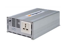


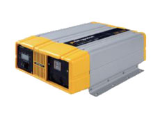
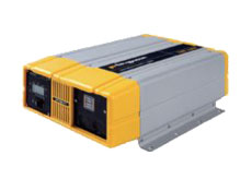
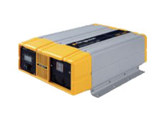
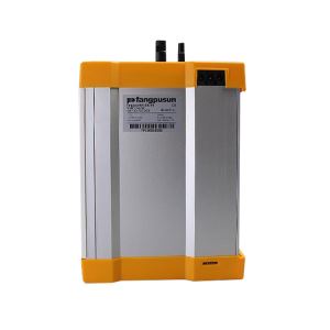
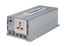
FP-S-600W Inverter
-
Min Order
1
-
Product Unit
Pieces
-
Origin
China Mainland
-
Payment


- Contact Now Start Order
- Favorites Share
- Description
Product Detail
DC to AC Power inverter manual

MODEL: F P-S-600
Pure sine wave output (<2% THD)
Input & Output fully isolation design.
High Efficiency 87% ~ 90%.
High surge in motor start capacity.
5-stage thermal control fan.
Frequency 50/60HZ switchable.
Auto restart.
Small size.

Firstly, thank you for purchase our product.Please read this manual carefully before
installing or using this product.

Introduction
This model is used in a wide range of application including remote homes, RVs, sailboats and powerboats.
It will operate most televisions and VCR, personal computers, small appliances and tools such as drills, sanders, grinders, mixers and blenders.To get the most out of the power inverter, it must be installed and used properly. Please read the instructions in this manual before installing and using this model.
Quick hook Ð up and testing
If you would like to quick hook-up the power inverter and check its performance before going ahead with your installation, please follow these guidelines:
1. Unpack and inspect the power inverter, check to see that the power switch is in the OFF position.
2. Connect the cables to the power input terminals on the rear panel of power inverter. The red terminal is positive (+) and black terminal is negative (-). Connect the cables into the terminals and tighten the wing nut to clamp the wires securely.
3. Connect the cable from the negative terminal of the inverter to the negative terminal of the power source. Make a secure connection.
Loosely tightened connectors result in excessive drop and may cause overheated wires and melted insulation.
4. Before proceed further, carefully check that cable you have just connected connects from the negative terminal of inverter to the negative output terminal of the power source.
Reverse polarity connection will blow a fuse in inverter and may permanently damage the inverter. Damage caused by reverse polarity connection is not covered by our warranty.
5. Connect the cable from the positive terminal of inverter to the positive terminal of the power source. Make secure connection.
You may observe a spark when you make this connection since current may flow to charge capacitors in the power inverter. Do not make this connection in the presence of flammable fumes, explosions or fire may result.
6. Set the power switch to the ON position. Check the meters and indicators on the front panel of the inverter.
If does not, check your power source and the connections to inverter. The other indicators should be off.
7. Set power inverter switch to the OFF position, the indicator lights may blink. Plug the test load into the AC receptacle on the front panel of the inverter. Please keep switch in off position.
8. Set power inverter switch to the ON position, the inverter should supply power to the load.
Installation
1. Where to install
The power inverter should be installed in a location that meets the following requirements:
a. Dry - Do not allow water to drip or splash on the inverter.
b. Cool - Ambient air temperature should be between 0? and 40?, the cooler the better.
c. Ventilated Ð Allow at least one inch of clearance around the inverter for airflow. Ensure the ventilation openings on the rear and bottom of the unit are not obstructed.
d. Safe - Do not install the inverter in the same compartment as batteries or in any compartment capable of storing flammable liquids such as gasoline.
2. Cables
DC to AC inverters require high amperage/low voltage DC power to low amperage/high voltage AC power. To operate properly connect inverter DC input terminals direct to battery with heaviest wire available see chart below:
Max Watts Out | Approx. Amps | Teq'dWire Gauge |
100W | 10A | #18 |
150W | 15A | #14 |
200W | 20A | #12 |
300W | 30A | #10 |
400W | 40A | #8 |
600W | 54A | #6 or 2×#10 |
3. Grounding
The power inverter has a lug on the rear panel chassis ground. This is to connect the chassis of the power inverter to the ground. The ground terminals in the AC outlets on the front panel of the inverter are also connected to the ground lug.The chassis ground lug must be connected to a grounding point, which will vary
depending on where the power inverter is installed. In a vehicle, connect the chassis ground to the chassis of the vehicle.
In a boat, connect to the boat's grounding systems. In a fixed location, connect the chassis ground lug to earth.
The neutral (common) conductor of the power inverter AC output circuit is connected to the chassis ground. Therefore, when the chassis is connected to ground, the neutral conductor will also be grounded .This conforms to national electrical code requirements that separately derived AC sources (such as inverters and generators) have their neutral tied to ground in the same way that the neutral conductor from the utility line is tied to ground at AC breaker panel.
The negative DC input of the power inverter is connected to the capacitance, then to the ground a positive ground DC system.
A positive ground DC system has the positive terminal of the battery connected to the chassis of the vehicle or to the grounding point.
Warning!
Do not operate the power inverter without connecting it to ground. Electrical shock hazard may result.
Operation
To operate the power inverter, turn it on using the ON/OFF switch on the front panel. The power inverter is now ready to deliver AC power to your loads. If you are operating several loads from the power inverter, turn them on separately after the inverter has been turned on. This will ensure that the power inverter does not have to deliver the starting currents for all the loads at once.
Controls and indicators
The ON/OFF switch turns the control circuit in the power inverter on and off. It does not disconnect power from the power inverter.
Operating limits
1.Overload / Auto re-start
The inverter would operate most AC loads within its power rating. If the load is over the specification, HT-S-600 will auto re-start 5 times, if not success, the inverter will shut down automatically.
2.Overtemp | Troubleshooting |
The buzz will be noisy if the temperature is | Television interference : |
too high, then the inverter will be shut down | Operation of the power inverter can |
automatically. Please re-set it after the | interfere with television reception on |
inverter got cooling. | some channels. If this situation occurs, |
Note1: The speed of fan operation will | the following steps may help to |
change 5-stage to follow the inverter | alleviate the problem. |
internal temperature. | -Make sure that the chassis ground |
| lug on the back of the power inverter is |
| solidly connected to the ground system |
3.Input voltage | of your vehicle, boat or home. |
The power inverter will operate from input | -Do not operate high power loads with |
voltage range 10V-15 (12V) or 20V Ð 30V | the power inverter while watching |
(24V). If the voltage drops too low(?1) or | television. |
raise too high(?2),the inverter will shut | -Make sure that the antenna feeding |
down automatically. Before shut down, buzz | your television provides an adequate |
noise will warn you. | (snow free) signal and that you are |
| using good quality cable between the |
| antenna and the television. |
?1:<10.3V(12V spec) or <20.6V(24V spec) | -Move the television as far away from |
| the power inverter as possible. |
?2:<15V(12V spec) or <30V(24V spec) | -Keep the cables between the battery |
| and the power inverter as short as |
| possible and twist them together with |
4.Frequency Switchable | about 2 to 3 twists per foot. This |
Adjust 50/60 HZ through the switchable | minimizes radiated interference from |
button.Buzz noise will remind you: | the cables. |
buzz1-50HZ |
|
buzz2-60HZ | Maintenance |
| Very little maintenance is required to |
| keep your inverter operating properly. |
Please turn on the inverter again when | You should clean the exterior of the |
you change frequency. | unit periodically with a damp cloth to |
| prevent accumulation of dust and dirt. |
| At the same time, tighten the screws |
| on the DC input terminals. |
Troubleshooting guide
Problem | possible cause | solution |
|
|
|
HIGH BATT | Battery voltage too high | Check for fault with |
SHUTDOWN |
| battery charging system. |
|
| Manually reset inverter |
|
| by turning switch to "on" |
|
| again. |
|
|
|
LOW BATT | Battery voltage too low | Charge battery. Manually |
BUZZ, |
| reset inverter by turning |
SHUTDOWN |
| switch to "on" again. |
|
|
|
OVERLOAD | Battery current too high, | Reduce load on the |
SHUTDOWN | probable AC overload | inverter. |
|
|
|
OVERTEMP | System over-temperature | Improve ventilation and |
BUZZ, |
| cooling and / or reduce |
SHUTDOWN |
| load on the inverter. |
|
|
|
SYSTEM | Overload or system | Ensure all loads and |
SHUTDOWN | hardware fault | disconnected. Try to |
|
| reset the unit by |
|
| switching to "on" if unit |
|
| still does not operate, |
|
| contact your distributor/ |
|
| merchant/ retailer for |
|
| service/ warranty |
|
| replacement. |
-
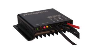
Solsum F Solar Charge Controller 1 Pieces / (Min. Order)
-
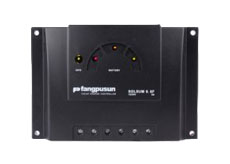
Solsum E Solar Charge Cotnroller 1 Pieces / (Min. Order)
-
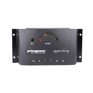
Solarix PRS Solar Charge Controller 1 Pieces / (Min. Order)
-
Solarix MPPT 1 Pieces / (Min. Order)
-
PR 1 Pieces / (Min. Order)
-
Solarix 1 Pieces / (Min. Order)
-
Tarom 1 Pieces / (Min. Order)
-
Tarom 4545 1 Pieces / (Min. Order)
-
FLEXmax MPPT 1 Pieces / (Min. Order)
-
Power Tarom 1 Pieces / (Min. Order)
-
Shunt 1 Pieces / (Min. Order)
-
Data Logger 1 Pieces / (Min. Order)
-
Off Grid Inverter 1 Pieces / (Min. Order)
-
Power Inverter 1 Pieces / (Min. Order)
-
Pure Sine Wave Inverter 1 Pieces / (Min. Order)
-
DC To AC Inverter Inverter 1 Pieces / (Min. Order)

-
Grid 500W 1 Pieces / (Min. Order)
-
PA RC100 1 Pieces / (Min. Order)
-
PA15 1 Pieces / (Min. Order)
-
PRL3030 1 Pieces / (Min. Order)
 Favorites
-
 MPPT Solar Charge Controller
1 Pieces / (Min. Order)
MPPT Solar Charge Controller
1 Pieces / (Min. Order)
-
 Solarix PRS Solar Charge Controller
1 Pieces / (Min. Order)
Solarix PRS Solar Charge Controller
1 Pieces / (Min. Order)
-
 MATE TWO
1 Pieces / (Min. Order)
MATE TWO
1 Pieces / (Min. Order)
-
 HT-S-300W Inverter
1 Pieces / (Min. Order)
HT-S-300W Inverter
1 Pieces / (Min. Order)
-
PRL3030
1 Pieces / (Min. Order)
-
PA15
1 Pieces / (Min. Order)
-
PA RC100
1 Pieces / (Min. Order)
-
Grid 500W
1 Pieces / (Min. Order)
-
DC To AC Inverter Inverter
1 Pieces / (Min. Order)
-
Pure Sine Wave Inverter
1 Pieces / (Min. Order)
-
Power Inverter
1 Pieces / (Min. Order)
-
Off Grid Inverter
1 Pieces / (Min. Order)
-
Data Logger
1 Pieces / (Min. Order)
-
Shunt
1 Pieces / (Min. Order)
-
Power Tarom
1 Pieces / (Min. Order)
-
FLEXmax MPPT
1 Pieces / (Min. Order)
-
Tarom 4545
1 Pieces / (Min. Order)
-
Tarom
1 Pieces / (Min. Order)
-
Solarix
1 Pieces / (Min. Order)
 Frequent updates ensuring high quality data
 Over 5000 customers trust us to help grow their business!


 Menu
Menu